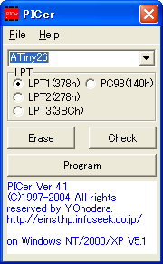
- To excute, double click "PICer.exe".
- Select PIC type to write.
- Select LPT to use.
- Erase button: erasing program
If PIC chip has factory OSC calibration data, PICer keep it. - Check button: checking blank
- Program button: writing program
PICer check to connect the circuit when you push the button. If no connection, you will see a error message "Error: Not ready LPT port!". Check the circuit and select proper LPT port.
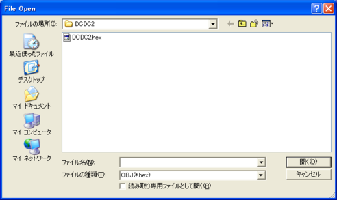
When PICer detect the circuit, you will see popup file open window. You can select a HEX file.
PICer automatically detect HEX format. Supported format is INHX32, INHEX16 and INHX8M.
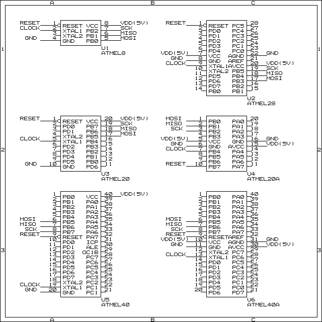
Special note for ATMEL
- .eep file has data area of ATMEL. Put it on same directory .hex file.
- .hex file doesn't have FUSE of ATMEL.
Make .cfg file to set FUSE with notepad tool.
See sample.cfg file.
Example test.cfg:LOCK=3 RCEN=0
- The head semicolon is comment.
- Each line has a LOCK or a FUSE.
- You can write LOCK and FUSE in lines without order.
- You can erase LOCK in ATMEL.
- You can't erase FUSE in ATMEL.
- Caution!: Do NOT set RSTDISBL=0, PICer will not able to re-write.
- Caution!: Do NOT set PLLCK=0, PICer will not able to re-write.
- PICer(Low Voltage serial method) can't change SPIEN.
| AT90S1200 | AT90S1200A | AT90S2313 | AT90S2323 | AT90S2343 | AT90S4433 | AT90S8515 | AT90S8535 | |
| LOCK=0 | o | o | o | o | o | o | o | o |
| LOCK=2 | o | o | o | o | o | o | o | o |
| LOCK=3 | O | O | O | O | O | O | O | O |
| FSTRT=0 | x | x | x | O | x | x | x | O |
| FSTRT=1 | x | x | x | o | x | x | x | o |
| RCEN=0 | x | x | x | x | O | x | x | x |
| RCEN=1 | x | x | x | x | o | x | x | x |
| BODLEVEL=0 | x | x | x | x | x | o | x | x |
| BODLEVEL=1 | x | x | x | x | x | O | x | x |
| BODEN=0 | x | x | x | x | x | o | x | x |
| BODEN=1 | x | x | x | x | x | O | x | x |
| CKSEL=0 | x | x | x | x | x | o | x | x |
| CKSEL=1 | x | x | x | x | x | o | x | x |
| CKSEL=2 | x | x | x | x | x | O | x | x |
| CKSEL=3 | x | x | x | x | x | o | x | x |
| CKSEL=4 | x | x | x | x | x | o | x | x |
| CKSEL=5 | x | x | x | x | x | o | x | x |
| CKSEL=6 | x | x | x | x | x | o | x | x |
| CKSEL=7 | x | x | x | x | x | o | x | x |
| ATtiny12 | ATtiny15 | ATtiny2313 | ATtiny26 | |
| LOCK=0 | o | o | o | o |
| LOCK=2 | o | o | o | o |
| LOCK=3 | O | O | O | O |
| FSTRT=0 | x | x | x | x |
| FSTRT=1 | x | x | x | x |
| RCEN=0 | x | x | x | x |
| RCEN=1 | x | x | x | x |
| BODLEVEL=0 | o | o | x | o |
| BODLEVEL=1 | O | O | x | O |
| BODLEVEL=4 | x | x | o | x |
| BODLEVEL=5 | x | x | o | x |
| BODLEVEL=6 | x | x | o | x |
| BODLEVEL=7 | x | x | O | x |
| BODEN=0 | o | o | x | o |
| BODEN=1 | O | O | x | O |
| CKSEL=0 | o | O | o | o |
| CKSEL=1 | o | o | o | O |
| CKSEL=2 | O | o | O | o |
| CKSEL=3 | o | o | o | o |
| CKSEL=4 | o | x | o | o |
| CKSEL=5 | o | x | o | o |
| CKSEL=6 | o | x | o | o |
| CKSEL=7 | o | x | o | o |
| CKSEL=8 | o | x | o | o |
| CKSEL=9 | o | x | o | o |
| CKSEL=A | o | x | o | o |
| CKSEL=B | o | x | o | o |
| CKSEL=C | o | x | o | o |
| CKSEL=D | o | x | o | o |
| CKSEL=E | o | x | o | o |
| CKSEL=F | o | x | o | o |
| RSTDISBL=0 | o | o | o | o |
| RSTDISBL=1 | O | O | O | O |
| SPMEM=0 | x | x | O | x |
| SPMEM=1 | x | x | o | x |
| DWEN=0 | x | x | o | x |
| DWEN=1 | x | x | O | x |
| EESAVE=0 | x | x | O | O |
| EESAVE=1 | x | x | o | o |
| WDTON=0 | x | x | o | x |
| WDTON=1 | x | x | O | x |
| CKDIV8=0 | x | x | O | x |
| CKDIV8=1 | x | x | o | x |
| CKOUT=0 | x | x | o | x |
| CKOUT=1 | x | x | O | x |
| PLLCK=0 | x | x | x | o |
| PLLCK=1 | x | x | x | O |
| CKOPT=0 | x | x | x | o |
| CKOPT=1 | x | x | x | O |
| SUT=0 | x | x | o | o |
| SUT=1 | x | x | o | o |
| SUT=2 | x | x | O | O |
| SUT=3 | x | x | o | o |
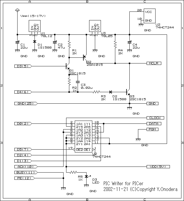
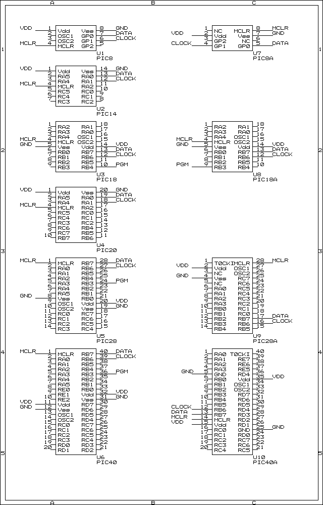
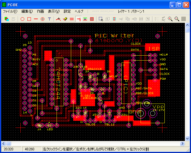
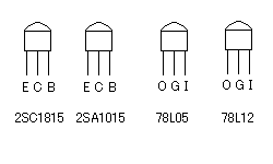
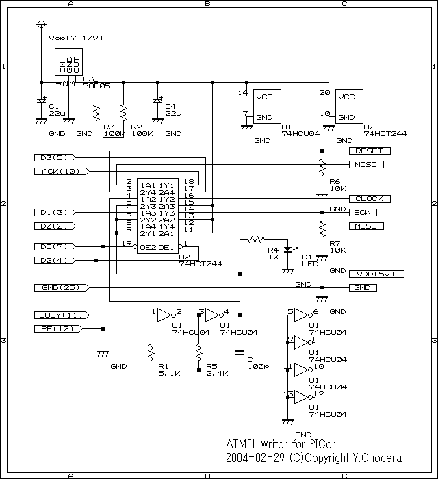
 Parts list